ESP32 node monitor

Step 2 Hook-up the ESP32

Connect the USB port of the developer board with your computer.

You’ll see the red led on the board light-up.

The next step, setting the correct port settings, I’m not sure if it is required or not. Go to your device manager on your computer (shown is the device manager of Windows10. Right click on the Silicon Labs USB port select properties. Under port setting, you can change the speed to 115200 bits per second.


Step 3 Load a test program

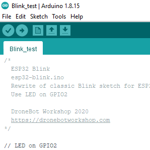
I loaded the “blink” test program (from Dronebot-workshop.com)  into the Arduino IDE (just copy paste it).

Compile the code by clicking the check box on the top left side.

After a number of seconds it say “Done” at the bottom, and some info below in the black part. Now we know the code is ok.

/* ESP32 Blink esp32-blink.ino Rewrite of classic Blink sketch for ESP32 Use LED on GPIO2
DroneBot Workshop 2020
https://dronebotworkshop.com
*/
// LED on GPIO2
int ledPin = 2;
void setup()
{
// Set LED as output
pinMode(ledPin, OUTPUT);
// Serial monitor setup
Serial.begin(115200);
}
void loop()
{
Serial.print(“Hello”);
digitalWrite(ledPin, HIGH);
delay(500);
Serial.println(” world!”);
digitalWrite(ledPin, LOW);
delay(500);
}

Step 4 Upload the code to the ESP

Just press the upload button to upload the code to the ESP.

The Arduino IDE tried to upload the code, but was clearly not able to.


At the end, it was quite simple: you have to press a small button on the board (labelled “IO0”) when the Arduino IDE tries to connect for the first time, to allow flashing.

Yeah, the blue led starts blinking.

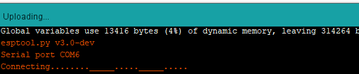
This eventually resulted in the following error:

Now we can start working on the node monitor in the next step.